The Building
The Hull was originally for an “A Class”, but, when the scale sails were made and fitted onto the hull, the boat was found to be seriously unbalanced.
The slightest breeze on the side of the boat would cause it to swing sharply up into the wind and stop, no amount of rudder would keep a straight course.
The mast was very near to its original position, but the Centre of Effort of the sails had been moved Aft due to the scale sails.
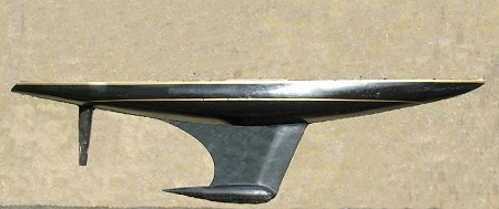
After much trial and error, an extension was made and fitted to the rear of the Keel , this has solved the problem almost completely, the boat now only turns into the wind, IF hit by a big gust, otherwise all is fine.
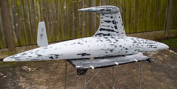
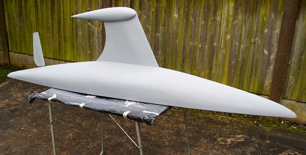
The Keel extension was filled and faired into the keel.
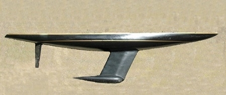
Before and after Keel modifications
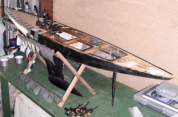
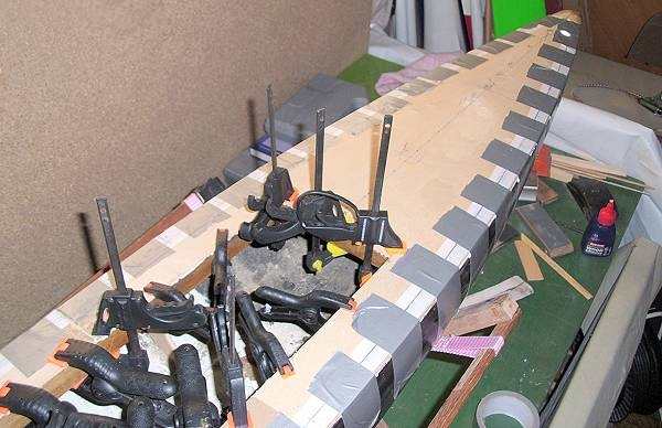
The Ply Deck.
The Deck Beams were levelled and a Radio Hatch formed to allow easy access to the gear, the existing Hatch was far too small.
A Plywood Deck, 1.5 mm thick was fitted next, the ply sheet was marked from underneath and cut out wide of the lines, to give a margin for fitting. Lots of clamps were used to hold the Ply sheet in place as well as strong sticky Tape, the whole assembly was left overnight to dry thoroughly. When the glue had dried, the excess Ply was cut away to match the sides of the Hull.
Hull finishing.
The surface of the Hull was very rough, paint had been applied in places which was peeling and flaking off, lots of sanding was required to get a smoother finish. Then, several coats of Filler, followed by lots more sanding, started to give a much better finish to the Hull.
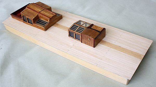
The Deck Cabins.
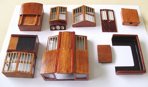
The Cabins were made next, not much information available about them, the sizes were taken from photographs on the Net and scaled up to suit the model. The Bars on the windows were because in 1935, Safety Glass was almost unobtainable.
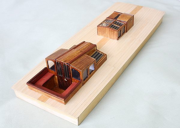
The first photo shows the parts for all the Cabins, the next two show the Cabins which are on the Deck Hatch.
The next photo shows the Instrument Panel, which is just in front of the Helmsman, this contained 5 Dials, which
gave the Helmsman full details about the boat in Real Time. On each side of the box were the Strain Gauges,
showing the Stresses on the Port and Starboard Shrouds. On the front, facing the Helmsman, were the Dials
showing the Wind Direction, the Wind Speed and a Mechanical Log device.
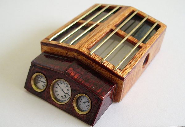
Alas, the Dials do not work on the Model, the largest Dial is only 8 mm in diameter!.
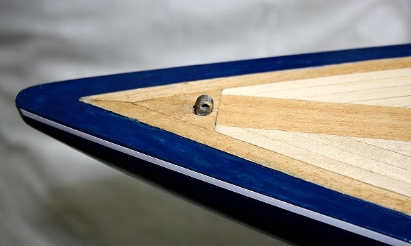
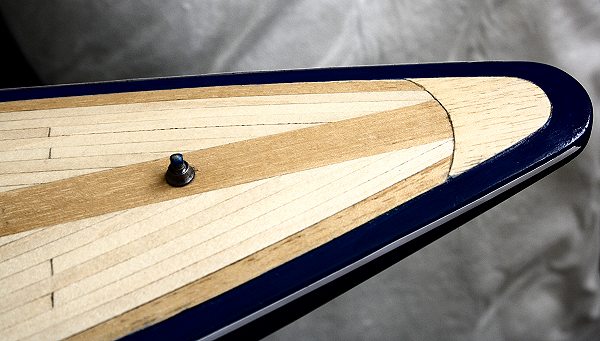
Deck Planking.
The Deck was planked with 4.5 mm wide Ash planks, 0.6 mm thick, this was for me the hardest part of the whole boat to do!. No room for error, everything in full view, very delicate material, it took a very long time to complete.
The King plank and the Margin planks are Obeche.
The first photo is of the Bow area, the second is of the Stern, these two areas are where most folk look first when viewing the deck, – – – because they are the hardest to get correct !.
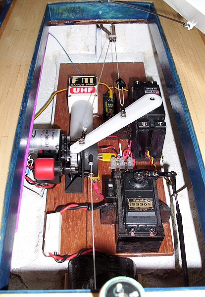
The Radio Gear.
This is the Radio Gear Hatch, looking Forward.
One winch is a lever arm one, a Hitec 815BB dealing with the Quad and the Jib.
The other one is an RMG 380EH hauling the Main Sail.
Both winches are connected onto the same channel on the Rx.
The Rudder is controlled by a 1/4 scale Futaba servo.
Power is supplied by a 6 volt 4 Ah Nicad.
The Tx was 459Mhz UHF, now using 2.4 Ghz.
M
To be Continued . . . . . . .